Address
304 North Cardinal St.
Dorchester Center, MA 02124
Work Hours
Monday to Friday: 7AM - 7PM
Weekend: 10AM - 5PM
Address
304 North Cardinal St.
Dorchester Center, MA 02124
Work Hours
Monday to Friday: 7AM - 7PM
Weekend: 10AM - 5PM

Abstract:In order to solve the problem of coexistence of malignant well leakage and spouting in high-temperature, high-pressure, high-sulfur, and narrow-density window formation drilling in the Jinesh gas field in Turkmenistan, Wen Zhang innovatively proposed and applied the fine pressure-controlled drilling integration technology based on the whole well circulation bridge slurry system. The technology accurately controls the fluctuation of downhole pressure through a closed loop, and successfully reduces the density of drilling fluid in the production section to 1.28 g/em³, effectively balancing the reservoir pressure and formation rupture pressure. The core technologies include: a “dynamic pressure profile” control model for narrow window formations; High pressure and low damage composite bridge slurry formula; The “pressure-flow coordination” rapid response control logic under the condition of co-storage of leakage and leakage. The field application effect is remarkable: the average mechanical drilling speed is increased by more than 59%, the non-productive time is reduced by more than 90%, the well leakage is reduced by more than 60%, and for the first time, high-quality tailpipe cementing is achieved under pressure control conditions (excellent rate greater than 97%). This integrated technology provides a reliable technical path and important practical basis for the safe and efficient drilling and completion of deep high-temperature, high-pressure and high-sulfur gas reservoirs.
Key words:managed pressure drilling,narrow pressure window,kick-loss coexistence,full well bridge slurry,drilling in complex formations,bottomhole pressure control,Turkmenistan Galkynysh Gas Field
Introduction
The Galkinesh gas field has the characteristics of high temperature, high pressure, high yield, and high sulfur content (“four highs”), and frequently encounters complex situations such as malignant well leakage and coexistence of spills during the drilling process. For example, Well 20 is directly exposed to complex pressure environments due to the failure of the casing in the early stage, resulting in the production section being directly exposed to complex pressure environments, and safe drilling is facing severe challenges. In view of the limitations of conventional drilling technology in terms of pressure plugging capacity, dynamic response speed and safety assurance under complex working conditions, the objectives of the integrated technical scheme of “whole well circulation bridge slurry system + refined closed-loop pressure control + fast response logic” are proposed: (1) Accurately define the safe drilling operation window 2; (2) construct an efficient response method for extremely complex working conditions; (3) Evaluate the comprehensive benefits of technology application. This scheme has been successfully applied to the drilling and completion operations of complex well sections of wells 60, 30 and 20 in the block.
1 .Key technologies for fine pressure control drilling
1.1 Working principle and system of fine pressure controlled drilling
The core technology of Managed Pressure Drilling (MPD) lies in the precise management of the bore annulus pressure profile, and its theoretical foundation is rooted in drilling hydraulics, involving the calculation and dynamic control of cyclic pressure consumption, equivalent ring density (ECD), excitation pressure and pumping pressure. The controllable backpressure is applied through the surface throttling system, combined with the real-time monitoring and regulation of drilling fluid density, displacement and drill string movement state, to achieve dynamic stability of the bottomhole pressure. The system composition and ground flow are shown in Figure 1.
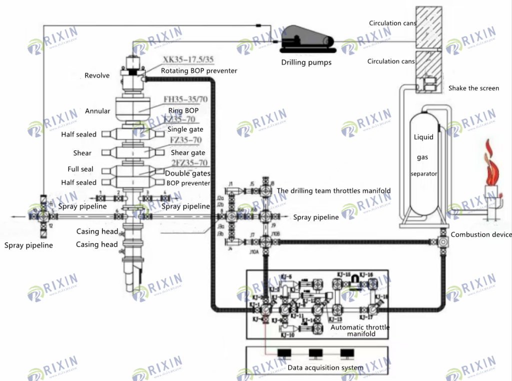
The MPD system consists of a rotary control head (RCD), an automatic throttle sink system (integrated micro-overflow detection skid, mass flow meter, pressure sensor), and a computer control system based on hydraulic real-time model and PID algorithm. The system continuously collects parameters such as vertical pressure, casing pressure, inlet and outlet flow, and drilling fluid performance, dynamically adjusts the opening of the throttle valve, and accurately maintains the set bottomhole pressure. Among them, the closed-loop flow control system and the early overflow detection (EKD) system are the key guarantees to achieve precise pressure control
1.2 Theoretical basis of fine pressure controlled drilling
The basic core theory used to describe the working principle of MPD consists of the following three sets of equations.
1.2.1 Wellbore pressure equilibrium equation
One of the key goals of MPD is to maintain the bottomhole pressure within a precise range by adjusting the wellhead backpressure. Bottom hole pressure is expressed as:

(1) In the formula: pm 1 well bottom pressure, Pa; p … 1. Wellhead backpressure, Pa; p — Drilling fluid density, kg/m³; h — the vertical depth of the well, m; P One cycle pressure consumption, Pa.
1.2.2 Fluid dynamics equations
(1) Continuity equation

(2) Momentum equation

(3) Energy equation

Where: a— the volume fraction of the k phase; p — k phase density, kg/m³; i— Phase k velocity, m/s; S—mass source term (e.g., gas intrusion rate), kg/(m³·s); F— Interphase force, kg/(m²·s²); T— temperature, °C; c — Specific heat capacity of constant pressure in phase k, J/(kg·°C); λ— thermal conductivity of the k phase, W/(m·°C); Φ — Volumetric heat source, W/m³.
1.2.3 Fuzzy self-tuning PID control equation
The backpressure of the wellhead is dynamically adjusted by the opening of the throttle valve, as shown in Equation (5):

Where: n(t)—the opening control amount of the throttle valve, adjust the back pressure of the wellhead, the range is usually 0~100% (corresponding to the valve is fully closed to fully open); e(t)— pressure error, the difference between the target bottom pressure and the regulated pressure, Pa; k,(t)— Ratio gain, amplifying the response speed of the current error, dimensionless; k; (t)— Integral gain, eliminating steady-state deviation caused by accumulation of historical errors, s⁻¹; k(t)— differential gain, predicting the trend of error change to suppress overshoot
By solving the equation (2) ~ equation (4), △p is calculated in real time, and then Pm and Pus are updated by using equation (1) … The target value is fed back to the throttle control system, and the reuse type (5) dynamically adjusts the throttle valve opening to achieve closed-loop control.
1.3 Fine pressure control drilling operation
(1) Pressure setting and adjustment: Set the target bottomhole pressure based on the actual drilling fluid density, formation pressure assessment and leakage monitoring data, and dynamically fine-tune it according to the downhole response (such as slight leakage or signs of gas intrusion).
(2) Drilling control: maintain a constant displacement drilling, and the control system maintains the constant riser pressure by adjusting the throttle valve opening. Real-time monitoring of inlet and outlet flow differentials enables accurate detection of early overflows/leaks.
(3) Connecting a single root/stopping pump: Execute the “soft stop pump” program, automatically control the back pressure compensation through the system, smooth transition, and avoid pressure excitation to induce leakage or pumping to induce overflow.
(4) Drilling control: Optimize the drilling speed, the system calculates the excitation/pumping pressure in real time and automatically adjusts the back-pressure compensation value to keep the bottom pressure stable in the safety window.
(5) Spray leakage coexistence response logic: start the diagnosis mode immediately, and quickly judge the main cause based on parameters such as gas flow, gas measurement value, and water tank level change. Take targeted measures (such as fine-tuning the backpressure to adjust the displacement/drilling fluid density) to avoid a vicious circle caused by violent pressure fluctuations.
2 Technical difficulties and countermeasures of pressure-controlled drilling
2.1 Analysis of difficulties
The Jinesh gas field in Turkmenistan has the characteristics of high temperature, high pressure, high yield and high sulfur content, and the safe drilling density window is narrow, and it is difficult to reasonably design the drilling fluid density to maintain constant control of wellbore pressure when drilling with conventional drilling technology, resulting in frequent encounters such as malignant well leakage and coexistence of spray leakage during the drilling process. According to the analysis, there are the following main technical difficulties in the process of pressure-controlled drilling in Galginesh gas field:
(1) Extremely narrow safety density window. The formation pressure equivalent density and rupture pressure equivalent density window in the production section are generally less than 0.03~0.05 g/cm³, and the density range of safe drilling fluid is extremely small.
(2) Frequent coexistence of spray and leakage. A slight fluctuation in pressure difference caused by a narrow window can easily induce well leakage or overflow, which often occurs alternately or at the same time.
(3) High temperature, high pressure and high sulfur environment. It puts forward extremely high requirements for the stability of drilling fluid performance, equipment reliability and personnel safety.
(4) Restrictions on the structure of the wellbore in the early stage. For example, the casing of well 20 failed to effectively seal the high-pressure layer, which further exacerbated the drilling risk in the production section.
Therefore, conventional drilling technology has limitations in terms of pressure plugging ability, dynamic response speed, and safety guarantee under complex working conditions.
2.2 Response measures
(1) Quickly detect the density window of the formation and adjust the wellbore pressure according to the density window Within the density window, fine pressure control technology is used to maintain constant control of wellbore pressure during the drilling, connecting columns, and drilling processes, so as to avoid complex leakage caused by wellbore pressure fluctuations.
(2) Use low-density drilling fluid to enter the main target layer to avoid the risk of serious well leakage and leakage overflow caused by high drilling fluid density; After drilling a leak, the wellbore pressure balance should be quickly established by reducing the pressure control value, displacement and drilling fluid density, and the formation fluid entering the wellbore should be removed in time to ensure the safety of the wellbore.
(3) Add sufficient sulfur remover to the drilling fluid, maintain the concentration of the sulfur remover ≥3%, and strengthen the monitoring of the pH value (or alkalinity) of the drilling fluid; At the same time, the wellbore pressure should be reasonably controlled to be slightly greater than the formation pressure, and the state of “micro leakage and micro-excess” should be maintained to avoid a large amount of formation fluid entering the wellbore and causing serious gas intrusion.
(4) The drilling fluid of the whole well bridge slurry with high temperature resistance is used to drill in the fracture section to optimize the particle size gradation, effectively seal the leakage channels of different scales, and maintain the good rheological properties and low reservoir damage characteristics of the drilling fluid. The typical formula is: 1%~2% YX-1+2%JD-8+2%HHH+
1%~2%GDJ-1 (total concentration 3%~6%).
3 On-site application and effect
The integrated technology has been successfully applied in three complex wells (wells 60, 30, and 20), which significantly shortens the processing time of complex situations, especially in well 20, which safely drills through the production layer and completes tailpipe cementing without the traditional safe density window.
The use of fine pressure control technology to explore the safety density window makes the determination of drilling fluid density more scientific and reasonable, which greatly reduces the degree of well leakage in the leaky section and reduces the difficulty of complex treatment of well leakage. The safety window of wells 60 and 30 is 1.32~1.49g/cm³, and the safety window of wells 20 is 1.33~1.43 g/cm³.
3.1 Field application
3.1.160 well: precise pressure control and leakage prevention
During the drilling process of 60 wells, when drilling fluid with a density of 1.42 g/cm³ was used to drill to a depth of 4117.92 m, the fine pressure control system detected the signs of leakage in real time through the outlet flowmeter and issued an alarm signal. Through the pressure control system, the displacement is accurately adjusted to 8.5 L/s, and the leakage phenomenon is quickly terminated, and the cumulative leakage is only 7.8m³. Subsequently, the density of drilling fluid was gradually reduced to 1.38 g/cm³, and the wellbore pressure and fluid state remained stable after the normal displacement was restored. This process verifies the efficiency and reliability of pressure control technology in early identification and timely suppression of trace leakage.
3.1.230 well: pressure control treatment well leakage
Well 30 suddenly leaked when drilling to 4325.45m with drilling fluid with a density of 1.32 g/em³, and the maximum leakage rate reached 20.5m³h. Drilling to casing shoes was carried out immediately after the well leakage, and the annulus liquid level was maintained by continuous lifting and irrigation technology, which effectively inhibited the risk of gas intrusion and overflow. 22% high-concentration composite plugging slurry is injected at the casing shoe, and 3 MPa constant sleeve pressure is applied with the help of the pressure control system for circulation and plugging. Subsequently, drilling was resumed after the pump was drilled down to the bottom of the well, and the 1 MPa cycle was verified to have no aftereffect.
The plugging and post-treatment took only 12 hours, which was significantly better than the average disposal time under similar working conditions of adjacent wells, reflecting the efficiency and safety guarantee ability of pressure control in the treatment of complex well leakage.
3.1.320 well: extremely narrow window drilling completion
In the process of drilling and completion of Well 20, facing the challenge of extremely narrow formation pressure window, the pressure control system plays an important role in many key nodes.
(1) Low-density drilling and gas intrusion suppression: actively reduce the density of drilling fluid to 1.28 g/cm³ at the stage from the drilling plug to the top of the tailpipe to achieve breakthrough low-density drilling. During the period, the pressure control system monitored the continuous slight overflow trend (the gas measurement value increased), and successfully inhibited the gas intrusion and ensured the stability of the wellbore by increasing the back pressure by about 2 MPa in real time, indicating that the pressure control technology has reliable safety maintenance ability under the condition of extreme low density.
(2) Loss of return leakage and pressure controlled bridge slurry drilling: Loss of return leakage occurred when drilling to 4215.57m, which was determined to be caused by low-pressure fracture zone based on the pressure evolution trend of the drilling section and real-time data. The site decision was made to continue drilling with a 4% concentration of the whole well circulating bridge slurry system, and to gradually increase the density to 1.33 g/em³ to cope with the risk of the lower high pressure gas layer. Under the combined control of this density and pressure control, only controllable microleakage (leakage speed less than 2m³/h) occurred during drilling, and finally safely crossed the target layer of the eleventh layer, and no serious leakage or loss of control occurred. Subsequently, the density was gradually restored to 1.37 g/cm³ to complete the subsequent footage. There was no malignant leakage or blowout out of control throughout the process.
(3) Tailpipe cementing under fine pressure control conditions: This well is the first time that tailpipe cementing operations are carried out under fine pressure control conditions. By accurately controlling the annulus air pressure profile to ensure the smooth replacement and setting of cement slurry10, the final cementing quality excellent rate reached 97.12%, the highest record in the region, which further verified the adaptability and superiority of fine pressure control technology in cementing operations.
3.2 Application Effects
3.2.1 Drilling efficiency has been significantly improved
As shown in Fig. 2, the average mechanical drilling speed of the MPD application wells (wells 60, 30, and 20) in the five production layers reached 2.00m/h, which was more than 59% higher than the average drilling speed of the adjacent wells of 1.26m/h.
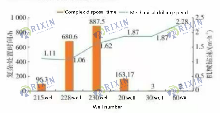
Fig. 2 Comparison of mechanical drilling speed and complex disposal time
Non-productive time (NPT): The average treatment time of MPD wells in the five production sections is only 56 h/well, which is significantly lower than the average of 555 h/well in adjacent wells, a decrease of more than 90%.
3.2.2 The well leakage control effect is remarkable
The cumulative leakage of MPD wells in the five production layers is 7.8m³ in 60 wells, 22.2m³ in 30 wells, and 664.2m³ in 20 wells. The average cumulative leakage of adjacent wells (e.g., wells 215, 228, and 230) in the same well section is as high as high
1616m³ 。 Although the leakage of 20 wells is relatively high, the safe drilling to reach the target level under extremely narrow window conditions has been achieved, and the leakage is still far lower than the average level of adjacent wells, and the treatment efficiency is greatly improved.
3.2.3 Well control safety, well wall stability and reservoir protection
(1) The density of drilling fluid in the production layer was successfully reduced to 1.28 g/cm³, which greatly reduced the bottom pressure difference and controlled the circulation equivalent in the safety window as much as possible, as shown in Fig. 3.
(2) The low pressure difference effectively reduces the intrusion damage of drilling fluid filtrate and solid relative reservoirs, which is conducive to reservoir protection.
(3) Precise pressure control maintains the mechanical stability of the wellbore wall, and there is no complication caused by wellbore instability during the application process.
(4) Well 20 drilled open-hole cement plugs from the lowest density of 1.28 g/cm³ to 4215m, circulating more than 20% of the total hydrocarbon base value and igniting and burning at the outlet, effectively balancing the formation pressure through closed-loop pressure control, and then adjusting the density to
1.33 g/cm³ to drill the main production layer. The developed “pressure-flow synergy” protocol ensures a fast and safe response when spraying and leaking coexists, demonstrating the safety of the technology under extreme conditions.
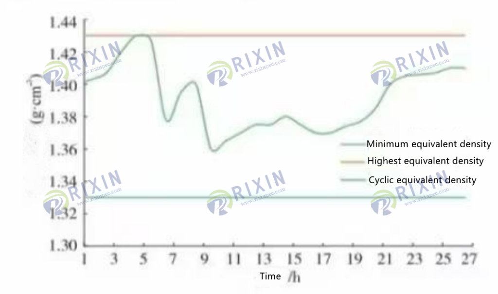
Figure 320 Well density window diagram
3.2.4 Cementing quality breakthrough
The quality of tailpipe cementing completed in well 20 under fine pressure control conditions reached 97.12%, far exceeding the conventional cementing level. The core contribution of fine pressure control is:
(1) Balance pressure: Accurately control the pressure profile of the annulus to avoid air channeling during condensation.
(2) Stable flow state: control the stable flow state of the replacement process and improve the replacement efficiency.
(3) Precise waiting for solidification: maintain reasonable annulus pressure to ensure the cement quality of cement stone2.
(4) Safety density window verification: Through the successful practice of integrated technology, the density range of drilling fluid in the main production section of Galginesh gas field is determined to be 1.28~1.40g/cm³. The lower limit of this density is 1.28 g/cm³, which can be safely applied by pressure control technology, and the upper limit is limited by the formation rupture pressure.
4 Conclusion
4 Conclusion
(1) The innovative and integrated application of whole-well cyclic bridge slurry system (FWBS) and fine pressure controlled drilling (MPD) technology has formed an effective solution to solve global problems such as malignant well leakage and coexistence of spray leakage in high-temperature, high-pressure, high-sulfur, and narrow-density window drilling.
(2) By accurately controlling the downhole pressure fluctuation and optimizing the formulation of high-pressure-low damage composite bridge slurry, the drilling fluid density in the production section of the gas field was safely reduced to 1.28 g/cm³ for the first time in this gas field, effectively reducing the well leakage loss by more than 60% and significantly reducing the risk of reservoir damage.
(3) The established “pressure-flow coordination” rapid response control system provides efficient safety guarantees for extremely complex working conditions such as spray and leakage coexistence, and reduces the processing time (non-production time) of complex situations by more than 90%.
(4) The integrated technology significantly improves the drilling efficiency, increases the average mechanical drilling speed of the applied well by more than 59%, and achieves high-quality tailpipe cementing (excellent rate >97%) under fine pressure control conditions for the first time, with an excellent cementing quality rate of 97.12%.
(5) The practical safety density window (1.28~1.40g/cm³) of the five-opening operation in the main production section has been verified, which provides a reliable technical paradigm and valuable practical support for the safe, efficient and economic development of high-temperature, high-pressure and high-sulfur gas reservoirs under similar complex geological conditions around the world.